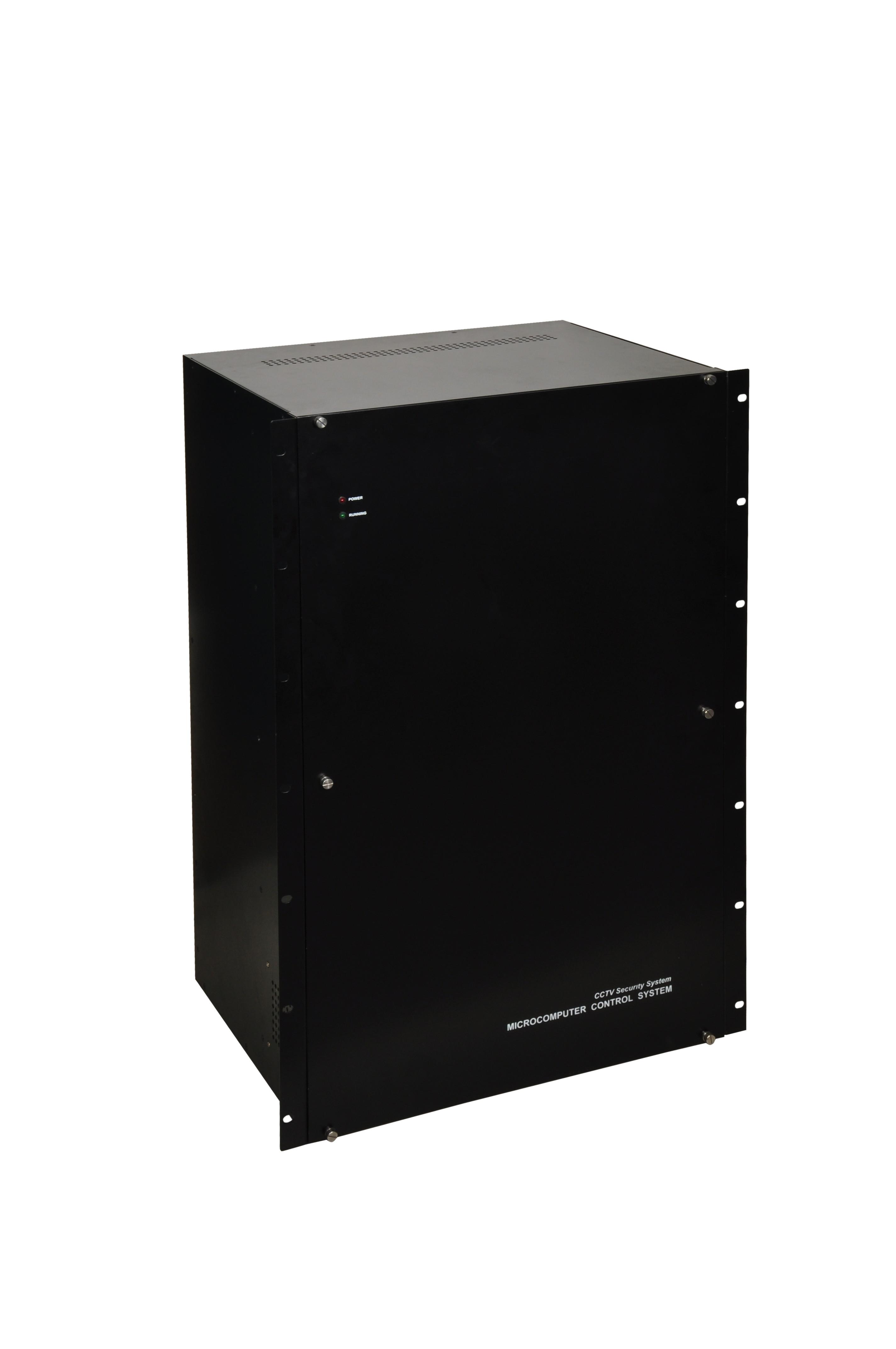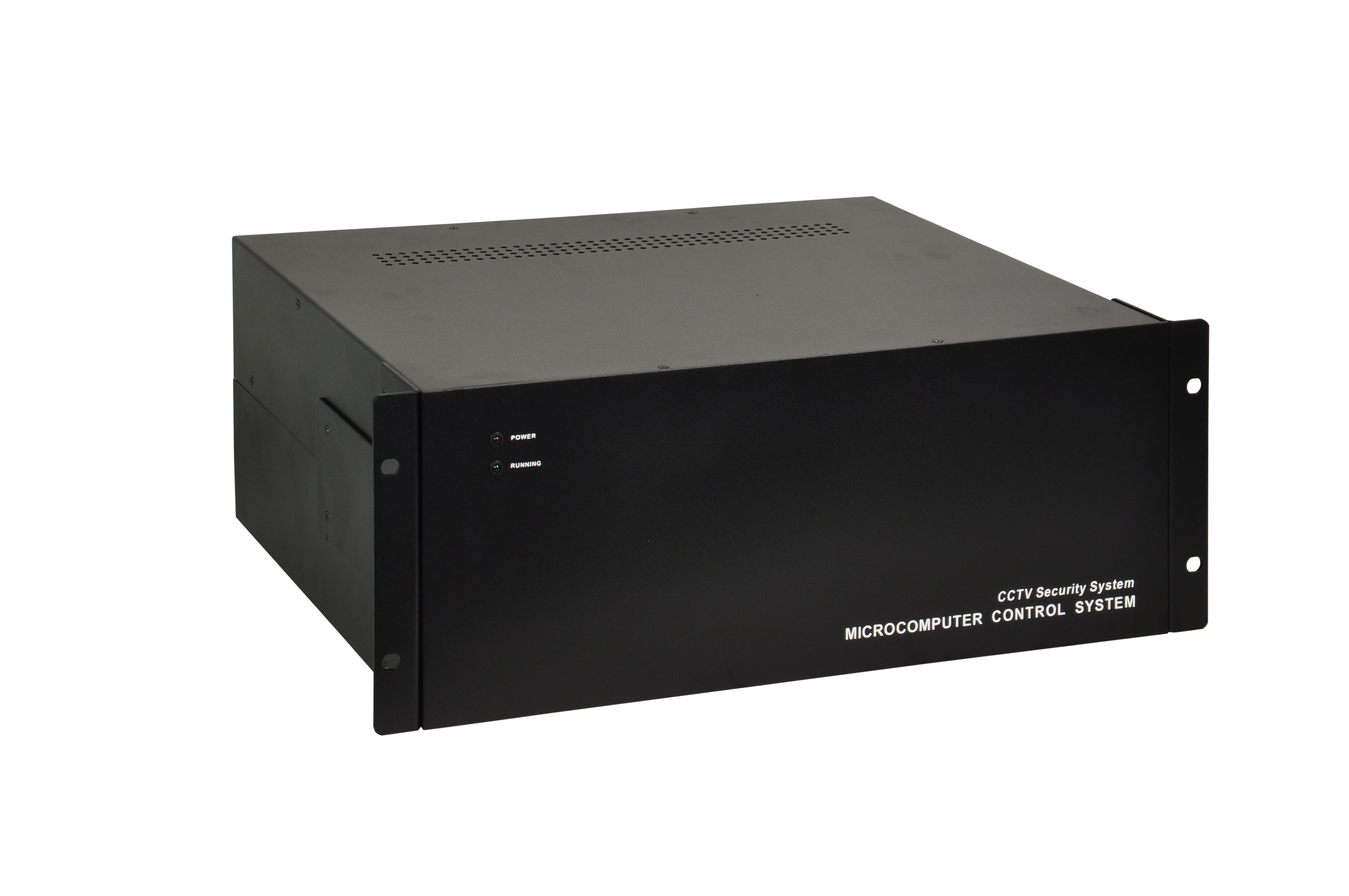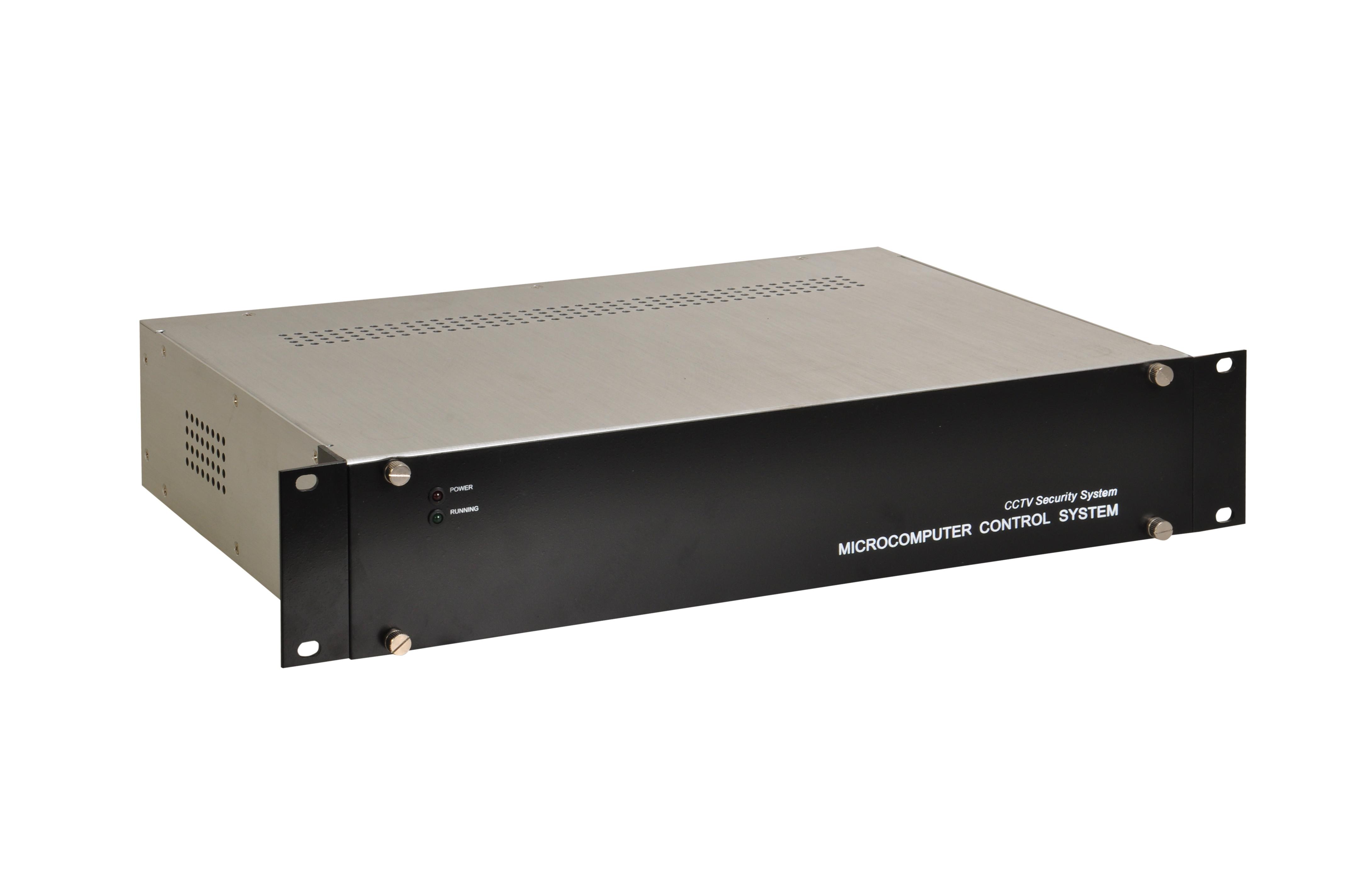
XLD9000 series small matrix
Product overview
·Maximum 64 inputs and 16 outputs, flexible configuration
·Perfect comprehensive menu settings
·Synchronous switching between audio matrix and video
·Convenient bus control structure
·8 user-selectable operation interfaces
·Can control various fixed-speed and variable-speed pan/tilts and high-speed balls
·Can control a variety of multi-view split video processors
·Can be integrated with hard disk video recorder, which can control front-end equipment and matrix switching
·Highly reliable RS-485 interface protection circuit
·The menu is displayed in Chinese and English
·Keyboard password
·Automatic alarm calling, up to 64 alarm inputs
·Perfect operation permission settings
·Automatic switching
·32 universal automatic switches
·32 simultaneous switches
·8 group switching
·Scheduled switching
·Camera title, date, time, system status screen display
Technical indicators:
·Bandwidth: 15MHZ
·Signal to noise ratio: -55dB
·Interference (input to input isolation): -70dB (typ. 3.58MHZ)
·Coupling (input to output isolation): -55dB (typ. 3.58MHZ)
·Differential phase: ≤1.5°
·Differential gain: ≤1.0%
·Tilt: ≤0.5%
·Gain: Rated ±1dB
·Return loss (input/output): ≥40dB
·Switching speed: less than 16 milliseconds (typical)
·Video input: BNC socket, composite video signal 0.5-1.5Vp-p
·Video output: BNC socket, 2-16 outputs
·Communication port: 3 RS-485 data ports, 1 RS-232 data port
·Baud rate: 9600Bits/S
·Screen display: display date, time, camera number, alarm status, camera title (8 white characters with black frame)
·Character settings: Chinese and English (China National Standard Level 2 font)
·Data memory: Setting information, inspection and configuration data can be saved for at least ten years
·Power supply voltage: 220V/50HZ
·Power: ≤15W
Mechanical indicators:
·Size: 89(height)X330(depth)X482(width)mm
·Weight: 11kg
·Chassis: anti-rust electrolytic plate oil injection
Environmental indicators:
·Operating temperature: -10~45 degrees Celsius
·Storage temperature: -30~70 degrees Celsius
·Humidity: Relative humidity 10%~90% non-condensing
·Vibration: 3g sine wave, 15Hz~2000Hz
·Vibration: 50g, 11ms, 1/2 sine wave
System Components
·Matrix switching chassis: Each chassis has 8 component slots, which can be inserted into video input components (VI), video output components (V0), and central processing unit modules (CPU). A single chassis can insert up to 4 video input components (VI), 2 video output components (V0), and 1 central processing unit module (CPU). The corresponding number of input and output channels is 64 inputs and 16 outputs.
·Central processing unit module XLD9000MCP: Use ROM resident operating software to control the entire system. Includes 3 RS-485 data ports (expandable).
·Video input module XLD9000VI: Each module provides 16 video inputs.
·Video output module XLD9000VO: In addition to providing monitor output channels, it can also add camera title and character information such as date and time, and control the position of characters. Each block provides 8 video outputs.
·Audio input module XLD9000AI: Provides 16 channels of audio input.
·Audio output module XLD9000AO: Provides 16 channels of audio output.
Function details:
·Modular design and flexible configuration
The system adopts a universal module structure and can connect up to 64 inputs and 16 outputs, which simplifies the upgrade and expansion of the matrix switching controller.
·Comprehensive menu settings
The system has an on-screen menu with selectable Chinese and English display modes, and can be programmed with a system keyboard and monitor.
·Keyboard password input
Each keyboard can be set with a password to restrict irrelevant personnel from using the system. This is a security measure for the system.
·Keyboard priority
Set the coding of each keyboard through the DIP switch behind the keyboard. The keyboard coding cannot be repeated in a system. Keyboard No. 0 has the highest level and keyboard No. 8 has the lowest level. When two keyboards control a decoder at the same time, the system executes the instructions of the keyboard with the higher level.
·Meet various switching requirements of users
Manual switching; automatic switching; universal automatic switching; synchronous switching; group switching
·System permission settings:
The permissions between keyboard, monitor, camera are clearly defined, further enhancing the security of the system. System permissions include: keyboard permission to the monitor; monitor permission to the camera; keyboard permission to control the camera; keyboard permission to switch the camera; keyboard permission to the defense zone
·Screen display can be selected
Date, time, camera number, camera title and monitor alarm status can be inserted on each video output. The date format is year/month/day, and the screen display uses white characters with black frames to increase the readout effect when the lighting changes. This system provides users with camera text control and date and time control. Text controls include horizontal and vertical shifting. Users can assign text descriptions to specific cameras, which helps operators identify the scene, as is required in multi-story buildings.
·Front-end device control
At the camera site, the decoding driver can control each camera's pan/tilt, motorized lens, auxiliary functions, preset points and automatic cruise paths.
·Alarm input and output
It comes with a 32-channel alarm input interface, and the alarm input and output can be expanded to 64 channels through the XLD9092 16-channel alarm interface box system.
·Automatic call of alarm
The programmable alarm input can call any video input point to any video output with any dwell time. It can call a preset point and an auxiliary switch for each alarm input with any auxiliary switch response time.
·Automatic alarm output
After the system detects any one or more alarm input signals, it will automatically respond and output through the alarm output port (one normally open and one normally closed switch) to control the video recorder or other external equipment. The maximum load capacity of the contacts: 7A/250VAC.
·Alarm status display
The screen displays the alarm input port, the called camera, the monitor used, and the system records alarm information.
·Communication status indicator:
When the connection between the device and the matrix host is normal, the communication indicator light flashes to facilitate the installation personnel to judge the system communication status.
·Four communication interfaces
The system provides 4 communication interfaces with a baud rate of 9600Bits/s, and forms a complete system with other devices.
CODE1 Bidirectional RS485 is used to connect keyboards and alarm interface boxes
CODE2 One-way RS485 is used to connect decoders and code converters
CODE3 bidirectional RS485 is used to connect other matrix to form a satellite matrix network
CODE4 Alternate
·Audio matrix switching
The audio matrix switching box is a full-crossover complete matrix system that switches synchronously with the video.
·Data storage
All user programming data such as system permissions, switching settings, titles, alarm calls and other data are stored in the system's internal memory and can be saved for at least 10 years in the event of a power outage.
Technical indicators:
·Bandwidth: 15MHZ
·Signal to noise ratio: -55dB
·Interference (input to input isolation): -70dB (typ. 3.58MHZ)
·Coupling (input to output isolation): -55dB (typ. 3.58MHZ)
·Differential phase: ≤1.5°
·Differential gain: ≤1.0%
·Tilt: ≤0.5%
·Gain: Rated ±1dB
·Return loss (input/output): ≥40dB
·Switching speed: less than 16 milliseconds (typical)
·Video input: BNC socket, composite video signal 0.5-1.5Vp-p
·Video output: BNC socket, 2-16 outputs
·Communication port: 3 RS-485 data ports, 1 RS-232 data port
·Baud rate: 9600Bits/S
·Screen display: display date, time, camera number, alarm status, camera title (8 white characters with black frame)
·Character settings: Chinese and English (China National Standard Level 2 font)
·Data memory: Setting information, inspection and configuration data can be saved for at least ten years
·Power supply voltage: 220V/50HZ
·Power: ≤15W
Mechanical indicators:
·Size: 89(height)X330(depth)X482(width)mm
·Weight: 11kg
·Chassis: anti-rust electrolytic plate oil injection
Environmental indicators:
·Operating temperature: -10~45 degrees Celsius
·Storage temperature: -30~70 degrees Celsius
·Humidity: Relative humidity 10%~90% non-condensing
·Vibration: 3g sine wave, 15Hz~2000Hz
·Vibration: 50g, 11ms, 1/2 sine wave
System Components
·Matrix switching chassis: Each chassis has 8 component slots, which can be inserted into video input components (VI), video output components (V0), and central processing unit modules (CPU). A single chassis can insert up to 4 video input components (VI), 2 video output components (V0), and 1 central processing unit module (CPU). The corresponding number of input and output channels is 64 inputs and 16 outputs.
·Central processing unit module XLD9000MCP: Use ROM resident operating software to control the entire system. Includes 3 RS-485 data ports (expandable).
·Video input module XLD9000VI: Each module provides 16 video inputs.
·Video output module XLD9000VO: In addition to providing monitor output channels, it can also add camera title and character information such as date and time, and control the position of characters. Each block provides 8 video outputs.
·Audio input module XLD9000AI: Provides 16 channels of audio input.
·Audio output module XLD9000AO: Provides 16 channels of audio output.
Function details:
·Modular design and flexible configuration
The system adopts a universal module structure and can connect up to 64 inputs and 16 outputs, which simplifies the upgrade and expansion of the matrix switching controller.
·Comprehensive menu settings
The system has an on-screen menu with selectable Chinese and English display modes, and can be programmed with a system keyboard and monitor.
·Keyboard password input
Each keyboard can be set with a password to restrict irrelevant personnel from using the system. This is a security measure for the system.
·Keyboard priority
Set the coding of each keyboard through the DIP switch behind the keyboard. The keyboard coding cannot be repeated in a system. Keyboard No. 0 has the highest level and keyboard No. 8 has the lowest level. When two keyboards control a decoder at the same time, the system executes the instructions of the keyboard with the higher level.
·Meet various switching requirements of users
Manual switching; automatic switching; universal automatic switching; synchronous switching; group switching
·System permission settings:
The permissions between keyboard, monitor, camera are clearly defined, further enhancing the security of the system. System permissions include: keyboard permission to the monitor; monitor permission to the camera; keyboard permission to control the camera; keyboard permission to switch the camera; keyboard permission to the defense zone
·Screen display can be selected
Date, time, camera number, camera title and monitor alarm status can be inserted on each video output. The date format is year/month/day, and the screen display uses white characters with black frames to increase the readout effect when the lighting changes. This system provides users with camera text control and date and time control. Text controls include horizontal and vertical shifting. Users can assign text descriptions to specific cameras, which helps operators identify the scene, as is required in multi-story buildings.
·Front-end device control
At the camera site, the decoding driver can control each camera's pan/tilt, motorized lens, auxiliary functions, preset points and automatic cruise paths.
·Alarm input and output
It comes with a 32-channel alarm input interface, and the alarm input and output can be expanded to 64 channels through the XLD9092 16-channel alarm interface box system.
·Automatic call of alarm
The programmable alarm input can call any video input point to any video output with any dwell time. It can call a preset point and an auxiliary switch for each alarm input with any auxiliary switch response time.
·Automatic alarm output
After the system detects any one or more alarm input signals, it will automatically respond and output through the alarm output port (one normally open and one normally closed switch) to control the video recorder or other external equipment. The maximum load capacity of the contacts: 7A/250VAC.
·Alarm status display
The screen displays the alarm input port, the called camera, the monitor used, and the system records alarm information.
·Communication status indicator:
When the connection between the device and the matrix host is normal, the communication indicator light flashes to facilitate the installation personnel to judge the system communication status.
·Four communication interfaces
The system provides 4 communication interfaces with a baud rate of 9600Bits/s, and forms a complete system with other devices.
CODE1 Bidirectional RS485 is used to connect keyboards and alarm interface boxes
CODE2 One-way RS485 is used to connect decoders and code converters
CODE3 bidirectional RS485 is used to connect other matrix to form a satellite matrix network
CODE4 Alternate
·Audio matrix switching
The audio matrix switching box is a full-crossover complete matrix system that switches synchronously with the video.
·Data storage
All user programming data such as system permissions, switching settings, titles, alarm calls and other data are stored in the system's internal memory and can be saved for at least 10 years in the event of a power outage.